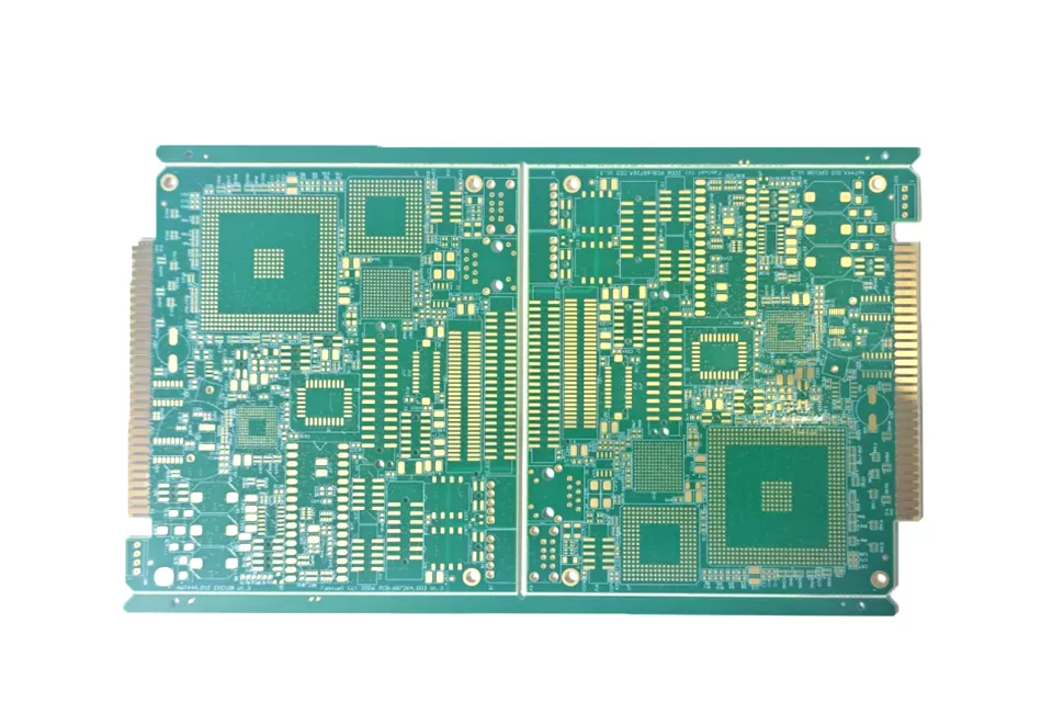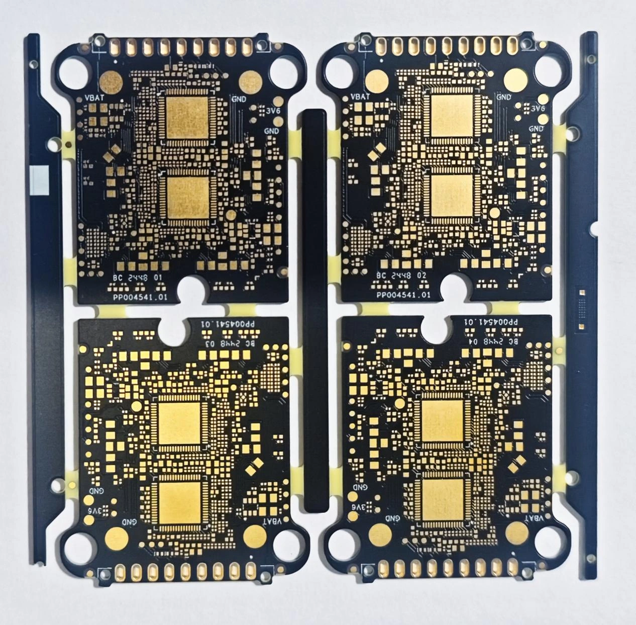



A battery management system board sits between the cells and the rest of the system. It carries the pack current, measures cell voltages, and must keep the high-voltage side away from the low-voltage side.
Three requirements drive the design: current capacity, isolation, and heat. Each one changes the board, and they often conflict.
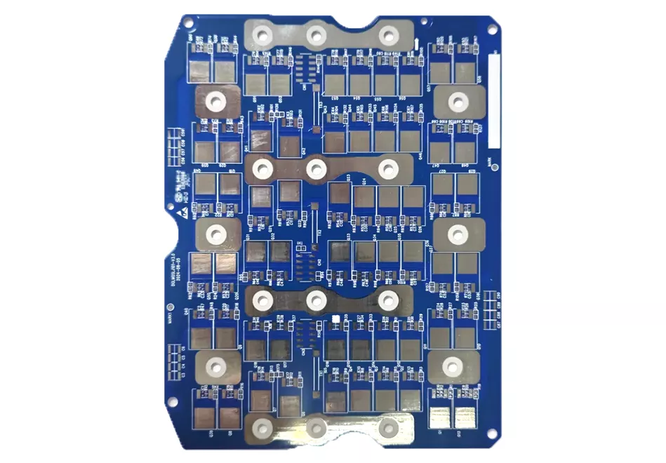
Current capacity
Pack current sets the copper. A 100 A pack needs wide traces or busbars; a 400 A pack usually needs both.
- 1 oz copper is rarely enough above 20–30 A continuous.
- 2–4 oz copper is common for 50–150 A.
- Above that, use busbars, shunts or multiple parallel paths.
Current density depends on allowable temperature rise, ambient temperature and airflow. A trace that is adequate in still air may fail in a sealed enclosure.
Isolation
High-voltage packs need creepage and clearance between the HV and LV domains. The rules come from the applicable standard (IEC 60664, IEC 62368 or automotive standards), not from the fabricator.
Design points:
- Define the working voltage and the pollution degree.
- Keep the isolation barrier continuous; no traces cross it.
- Use slots or cutouts where the required creepage exceeds the available surface distance.
- Respect the CTI of the laminate; contaminated or humid surfaces reduce it.
- Keep the barrier away from board edges and mounting holes.
The fabricator can build the slot; only the designer can define the distance.
Thermal path
MOSFETs and shunts generate heat. The path is die → package → copper → via → heatsink or ambient.
Options:
- Heavy copper planes spread heat.
- Thermal vias move heat to the other side.
- Insulated metal substrate (IMS) boards spread heat through the metal base.
- Thermal interface material couples the board to a heatsink.
A thick copper plane with no path to a heatsink only delays the temperature rise. The thermal path must be complete.
DFM rules
| Parameter | Typical requirement | Note |
|---|---|---|
| Copper weight | 2–4 oz for 50–150 A | Check etch minimum |
| Creepage/clearance | Per standard | Designer responsibility |
| Isolation slot | Wider than the router bit | Adds cost |
| Thermal vias | Under the MOSFET pad | Check fill and void |
| Solder mask | High CTI, no mask in press-fit | Contamination risk |
| Warpage | Balanced copper | Thick copper warps |
Assembly and test
- Press-fit connectors need controlled holes and no mask intrusion.
- Shunts may need a Kelvin connection for accurate measurement.
- High-voltage test requires a safe fixture and clear labeling.
- Conformal coating may be needed for humidity; check CTI and connector compatibility.
FAQ
Can I use 1 oz copper for a 100 A pack?
Not for the main current path. Use 2–4 oz or a busbar. The exact limit depends on temperature rise and airflow.
Who defines creepage and clearance?
The designer, based on the applicable standard and the working voltage. The fabricator only builds what is drawn.
Is IMS better than FR-4 for BMS?
For heat spreading, often yes. For high-voltage isolation and complex routing, FR-4 with thick copper may be better. Review both.
Does conformal coating affect isolation?
It can improve humidity performance but does not replace the required creepage and clearance.
Current, isolation and heat pull in different directions, and the compromise usually shows up at first article. Send the pack voltage, current and the standard you are designing to, and we will review the barrier and the thermal path together.