


Controlled impedance is verified on a coupon, not on the product board. The coupon is a test pattern built on the same panel, with the same stackup and process, so its measurement can stand in for the product traces.
If the coupon does not match the product — different layer, different line width, different copper thickness, different finish — the report may look good and still tell you nothing about the board you shipped.
This article covers coupon design, TDR measurement, tolerance, and the reporting rules that prevent arguments.
What a coupon is
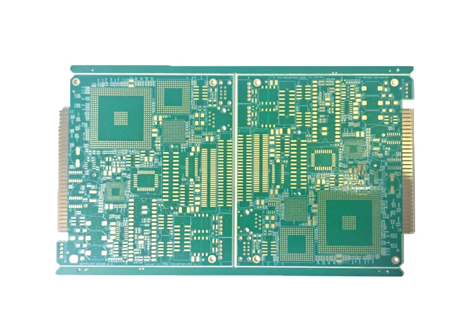
An impedance coupon is a set of test traces placed on the panel, usually at the edge or on a breakaway strip. It contains:
- Single-ended traces at the target impedance, typically 50 Ω.
- Differential pairs at the target impedance, typically 90 Ω or 100 Ω.
- Coplanar or grounded coplanar structures if the design uses them.
- Probe or connector pads with ground references.
The coupon is measured after fabrication, usually with TDR. The result is reported per coupon and per lot.
Design rules
Match the product. The coupon must use the same stackup, same layer, same line width and spacing, same copper weight and same solder mask. A coupon built on a different layer tests a different dielectric thickness.
Use the same reference plane. The coupon's ground plane must be the same distance from the trace as in the product. A coupon with a closer plane will read a lower impedance.
Make it long enough. TDR needs a stable region to measure. A coupon that is too short cannot separate the launch from the line, and the reading includes the probe transition.
Provide a clean launch. Use GSG probes or SMA connectors with ground vias close to the signal via. A poor launch adds inductance and shifts the reading.
Place it where it survives. The coupon should be on a breakaway rail or a panel edge, not inside a customer area. It must be routed so it can be measured without cutting the product.
| Parameter | Typical requirement | Note |
|---|---|---|
| Coupon layer | Same as product trace | Different layer = different impedance |
| Line width/spacing | Same as product | Tolerance follows the etch process |
| Coupon length | 50 mm or more | Longer line, cleaner TDR plateau |
| Launch | GSG probe or SMA with ground | Poor launch shifts the reading |
| Finish | Same as product | Finish affects skin depth at high frequency |
| Tolerance | ±10%, tighter on request | State the measurement uncertainty |
How TDR measures impedance
A TDR instrument sends a fast step into the coupon and records the reflected voltage. The reflection coefficient is converted to impedance along the line.
Key settings:
- Rise time. A faster edge resolves finer features but is more sensitive to launch and cable. The instrument rise time should be stated in the report.
- Reference plane. Calibrate at the probe tip, not at the instrument port.
- Gating. Gate the measurement to the coupon line, excluding the launch and the far-end open.
- Averaging. Use enough averages to remove noise, and state the setting.
The report should include the coupon ID, layer, nominal impedance, measured value, tolerance, instrument rise time, and the measurement location along the line.
Tolerance and disputes
A common specification is ±10%. Tight designs may ask for ±8% or ±5%. Before agreeing, check three things:
- The fabricator's etch and lamination capability at that line width.
- The measurement uncertainty of the TDR setup; a ±5% spec with ±3% uncertainty leaves little margin.
- Whether the coupon is measured with or without solder mask; the mask changes impedance by a few percent.
If the measured value is outside tolerance, the first question is whether the coupon matches the product. The second is whether the measurement was taken at a stable point. Only then is it a process issue.
Common mistakes
- Coupon built on a different layer than the product traces.
- Coupon line width adjusted to hit the target, not matching the product.
- Coupon too short to separate launch from line.
- No ground reference or a poor launch.
- Measuring before final finish, then comparing with a finished board.
- Reporting a single number without the measurement conditions.
FAQ
Does every order need a coupon?
For controlled-impedance boards, yes. The coupon is the evidence that the stackup and process produced the target impedance.
Can the coupon be on the same panel as the product?
Yes, that is the point. It should be on the same panel and same stackup, usually on a rail.
Is TDR the only method?
TDR is the standard production method. VNA and signal integrity simulation are used for design verification, not for lot acceptance.
What if the coupon passes but the product fails?
Then the coupon did not represent the product. Check layer, line width, reference plane and finish first.
What to send for an impedance review
- Stackup with target impedance per layer
- Single-ended and differential targets
- Coupon requirement and location
- Tolerance and measurement method
- Finish and mask requirement
- Acceptance class
Send your stackup for an impedance review, or review our HDI capability and multilayer capability.