


Heat is the silent killer of LED performance. As an LED product designer, you know that managing junction
Release the FR4-versus-aluminum decision against a quantified system thermal budget, the final mechanical interface and the intended circuit partition. The selected construction must hold LED junction temperature within the design target at worst-case input power, ambient temperature, enclosure condition, mounting tolerance and production variation.
FR4 remains appropriate for many LED drivers, control boards and distributed low-power arrays. An aluminum PCB or other insulated metal substrate becomes more attractive when the board must act as a controlled part of the heat path. In either case, substrate selection alone does not determine reliability. Copper spreading, dielectric thickness, component attachment, board-to-heatsink interface, clamping pressure, thermal interface material and airflow can dominate the result.
1. Define the System Thermal Budget Before Releasing the Stack-Up
Separate the electrical input power from the heat that the assembly must remove. The thermal model should use estimated heat dissipation at the operating current, not simply the LED's nominal wattage. The design margin also needs to cover LED bin variation, driver efficiency, ambient extremes, enclosure effects, contamination and degradation of the thermal interface over time.
Use the following relationship as the first-pass design check:
Junction temperature ≈ ambient temperature + heat dissipation × total junction-to-ambient thermal resistance
The total resistance is a chain: LED junction to thermal pad, solder joint, copper spreading area, PCB construction, board interface, heatsink and surrounding environment. Changing the substrate helps only the PCB portion of that chain. If the board is poorly coupled to the housing, or the thermal interface material is too thick, switching to a higher-conductivity dielectric may deliver less improvement than expected.
Information to lock before substrate selection
- Maximum ambient temperature inside the final luminaire or enclosure
- LED operating current, electrical input and estimated heat dissipation
- Maximum target junction temperature and required design margin
- LED package thermal-pad geometry and permissible solder voiding
- Available copper spreading area and board outline
- Board mounting method, fastener locations and allowable flatness
- Thermal interface material, compressed thickness and contact pressure
- Heatsink, enclosure, airflow and expected duty cycle
Without these inputs, specifying “FR4” or “3 W/m·K aluminum PCB” does not establish the operating junction temperature.
2. Compare the Complete Stack-Up, Not Only the Base Material
Use FR4 when routing and integration dominate the requirement
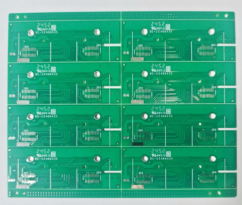
Specify FR4 when routing density, layer count, electrical isolation and component integration carry more weight than through-board heat transfer. Typical cases include LED driver circuitry, communication and control functions, sensor interfaces and architectures where the principal LED heat source is on a separate light-engine board.
FR4 can also support some LED arrays when power density is moderate and the thermal path is deliberately engineered. Useful measures include large copper areas, balanced copper, thermal vias beneath or around the exposed pad, reduced board thickness where mechanically acceptable and direct coupling to a chassis or heatsink.
However, the via design must be released as a manufacturing requirement, not left as a general drawing note. Via diameter, pitch, plating, fill or cap method and solder-mask treatment affect both thermal behavior and assembly yield. Open vias in a thermal pad can draw solder away from the component and increase voiding. For designs requiring multilayer routing together with thermal management, the stack-up should be reviewed with a multilayer PCB manufacturer before the mechanical design is frozen.
Use aluminum or IMS when the PCB is part of the controlled heat path
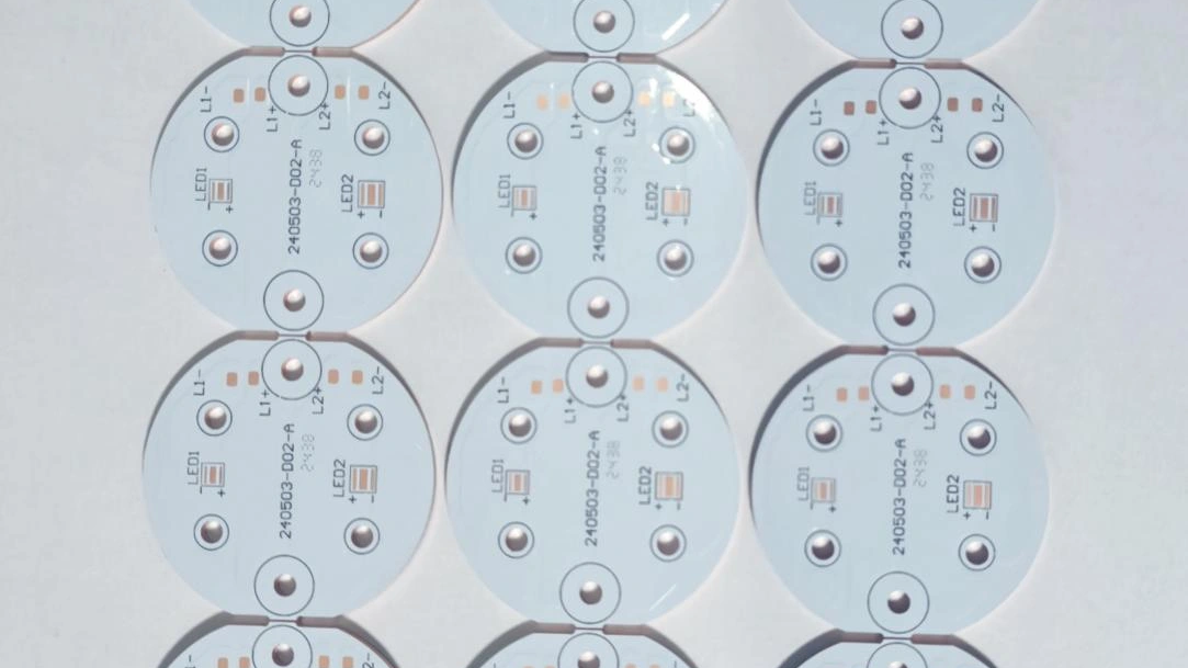
Specify an aluminum PCB when the LED PCB board must provide a short, repeatable path from the component land pattern into a housing or heatsink. Typical candidates include compact light engines, street-light modules, horticultural lighting, dense LED arrays and automotive lighting operating at elevated power density or ambient temperature.
The thermal bottleneck in a conventional metal core PCB is often the dielectric between the circuit copper and the metal base. Its thermal resistance depends on conductivity, thickness and effective heat-transfer area:
Thermal resistance of the dielectric ≈ dielectric thickness ÷ (thermal conductivity × transfer area)
This is why a conductivity value alone is not enough. A thinner qualified dielectric with appropriate isolation performance may produce a lower thermal resistance than a thicker material advertised with a higher W/m·K figure. The released specification should therefore identify the approved dielectric system or define both thermal and electrical performance requirements.
Base-metal thickness mainly supports heat spreading, rigidity and the mechanical interface. It does not compensate for poor contact with the housing. Flatness, mounting-hole position, burr control, surface condition and thermal-interface compression are production variables that should be considered with the thermal design.
For project review, Benchuang's metal core PCB manufacturer page lists the construction, dielectric, copper, isolation, geometry and cooling information needed to evaluate an IMS design.
FR4 vs. aluminum PCB comparison for LED projects
| Decision Factor | Placa de circuito impreso FR4 | Aluminum / IMS PCB | What the RFQ Should Define |
|---|---|---|---|
| Primary role | Electrical routing, isolation and multilayer integration | Electrical routing plus a controlled board-level heat path | Board function, heat sources and mechanical cooling route |
| Thermal path | Copper spreading and thermal vias usually carry heat through the board | Dielectric transfers heat from circuit copper to the metal base | Power map, target temperatures, interface and heatsink conditions |
| Circuit complexity | Better suited to multilayer routing and dense control circuitry | Commonly used for simpler circuit layers; complex IMS stack-ups require specific review | Layer count, stack-up, impedance and isolation requirements |
| Critical material input | Laminate system, Tg, copper construction and finished thickness | Dielectric system, thickness, thermal behavior, isolation and base metal | Approved material or performance-based acceptance limits |
| Assembly risks | Solder wicking through thermal vias, local hot spots and board warpage | Thermal-mass effects during reflow, flatness and interface consistency | Reflow profile, voiding criteria, panelization and fixture method |
| Mechanical integration | May require a separate heat spreader or chassis interface | Metal base can couple directly to a housing or heatsink | Hole tolerances, flatness, TIM, fasteners and contact pressure |
| Typical cost driver | Layer count, via structure, copper weight, material and panel utilization | Dielectric system, copper, base thickness, machining, isolation testing and panel utilization | Prototype, pilot and production quantities using the same released construction |
3. Selection Matrix for Common LED Product Architectures
The correct choice often follows circuit partition and heat density rather than the product label “LED lighting.”
| Product Architecture | Likely Starting Point | Reason | Qualification Focus |
|---|---|---|---|
| Driver, dimming or communication board | FR4 | Routing, isolation and component integration normally dominate | Creepage, copper temperature rise, magnetics, capacitor temperature and enclosure airflow |
| Distributed low-power LED strip or panel | FR4 or aluminum | Choice depends on LED spacing, copper area, installation surface and ambient temperature | LED temperature uniformity, local hot spots, mounting and long-length voltage drop |
| Compact high-output light engine | Aluminum / IMS | High heat density requires a short, repeatable path into the heatsink | Dielectric resistance, solder voiding, TIM thickness, flatness and clamping |
| Street light or horticultural module | Aluminum / IMS is common | Continuous duty and elevated output make thermal spreading important | Worst-case ambient, enclosure temperature, optical aging, moisture protection and field mounting |
| Automotive lighting module | Project-specific IMS or advanced construction | High heat density, vibration, packaging limits and transient conditions require system-level review | Thermal cycling, vibration, isolation, connector loading, traceability and approved material system |
| Separate driver and LED engine | FR4 driver plus aluminum LED light PCB | Each board can be optimized for its electrical and thermal function | Interconnect reliability, grounding, assembly sequence and thermal/mechanical interfaces |
For a custom LED PCB, compare candidate constructions using the same LED package, solder process, thermal interface, heatsink and operating condition. A bench comparison that changes several variables at once cannot isolate the benefit of the substrate.
4. What to Specify Before Requesting a PCB Quotation
A useful quotation must be tied to a released construction and the intended thermal interface. Send the PCB supplier enough information to check manufacturability without asking the factory to infer the product's thermal requirements.
- Manufacturing data: Gerber or ODB++ files, drill data, board drawing, revision and panel requirements
- Construction: FR4 or metal-base requirement, layer count, finished thickness, copper weight and approved material where applicable
- Thermal inputs: LED package, heat-source locations, estimated dissipation, maximum ambient and temperature targets
- IMS dielectric: required thermal performance, thickness, electrical isolation and approved system or qualification method
- Mechanical interface: board outline, mounting holes, flatness, burr limits, heatsink, TIM and clamping arrangement
- Electrical requirements: working voltage, creepage and clearance, isolation test and acceptance limits
- Surface and optical requirements: surface finish, solder mask, reflectance or discoloration expectations and marking
- Assembly requirements: component side, stencil, thermal-pad aperture, voiding criteria, reflow profile and any supplied components
- Commercial inputs: prototype, pilot and production quantities, target date, packaging and delivery destination
Where PCB fabrication and LED assembly are quoted together, also provide the BOM, pick-and-place file, assembly drawing and inspection requirements. Benchuang can review the complete scope through its PCB fabrication and PCBA support process.
Need a construction review for an LED module? Send the board files, heat-source information, dielectric or isolation requirements, mounting arrangement and order quantities. Request an engineering review and quotation.
5. FR4 and Aluminum PCB FAQ for LED Projects
Can thermal vias make FR4 perform like an aluminum PCB?
Thermal vias can materially improve an FR4 heat path, especially when they connect an exposed pad to a large copper region or external heat spreader. Whether they close the gap depends on via count, pitch, plating or fill, board thickness, copper area and the downstream interface. The comparison should be made using calculated thermal resistance and a representative assembled test, not substrate names alone.
Does a higher dielectric W/m·K rating always produce a cooler LED?
No. Dielectric thickness, contact area, copper spreading, solder joint, TIM and heatsink resistance all contribute. Review conductivity and thickness together, then validate the full stack. Also confirm that the dielectric meets the required electrical isolation and manufacturing process conditions.
Which IMS parameters should be controlled on the purchase specification?
Define the metal-base construction, dielectric system or approved equivalent, dielectric thickness, copper weight, finished board thickness, isolation or withstand requirement, flatness, machining tolerances, surface finish and applicable inspection records. If thermal performance is critical, agree on the test method and acceptance criteria rather than relying on a catalogue conductivity value.
Can an aluminum PCB use more than one circuit layer?
Multilayer IMS constructions are possible, but they should not be treated as a standard single-layer aluminum PCB with extra routing. The stack-up introduces additional dielectric and copper layers, changes the heat path and may require different lamination, isolation and reliability review. Submit the actual stack-up for feasibility confirmation.
What should be checked during a prototype thermal validation?
Use the released LED current, representative enclosure, production-intent TIM, heatsink, fasteners and airflow. Record ambient, board reference-point and LED case or solder-point temperatures after stabilization. Correlate the measurement method with the LED supplier's junction-temperature calculation, then repeat at worst-case operating and mounting conditions.